FDT in the Lifecycle of Industrial Robots
From production to diagnostics, FDT is the unifying tool supporting the life cycle of industrial robots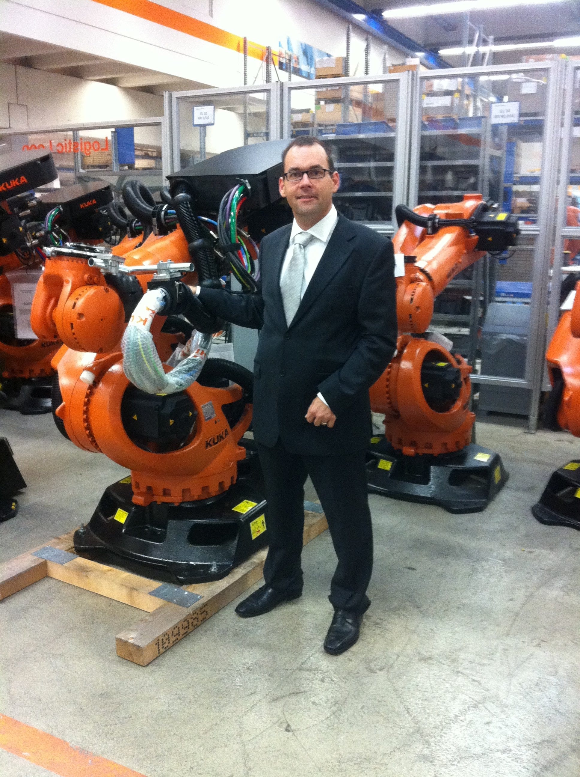 for manufacturing. For Kuka’s customers, the robot is delivered with the FDT/FRAME for commissioning.
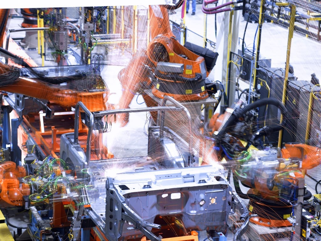
Industrial robots have very complex motion and general control requirements due to their increasingly advanced kinematics capabilities. In addition to its diverse array of drives, encoders, I/O modules, and internal networks, the robot control system must also integrate a wide variety of peripherals on the robot flange such as grippers or weld gun. This complete robotic package is then married to a higher-level control system from which it receives coordinating control signals, such as a program number to be executed or an emergency stop.
Requirements for a bus tool for industrial robots
Industrial robots are integrated into their industrial environment using a wide variety of fieldbuses. Often multiple fieldbuses are used in a single robotic application. Amidst this diversity of fieldbuses and devices, a common configuration and management tool is required.
Strengths of FDT Technology
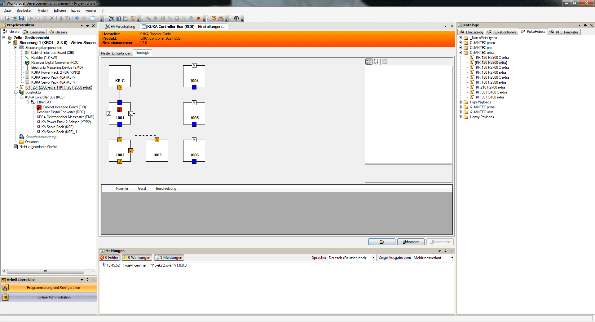
With KUKA, this unifying tool includes an FDT Frame Application. This FDT based tool saves all fieldbus-specific information that is generated during commissioning in a shared project. The FDT DTMs work seamlessly with one another, even though they are supplied by many different manufacturers. The very complex bus scenarios across multiple gateways can be configured without any difficulty thanks to the nested communications capability built into the FDT standard.
Initial commissioning during cabinet assembly
 A robot is commissioned in multiple phases. The initial commissioning takes place in the KUKA factory during the cabinet assembly. Based on the customer order, an FDT project is automatically created with factory settings. This includes the bus configuration for the drive technology with converters (of different size if necessary), various encoder units, special modules, and optional special accessories, such as I/O modules. With this configuration, the cabinet is fully ready to operate.
Addition of customer components on the construction site
System integrators or end users often provide the robot configuration with additional field devices, particularly tools that they can buy from third-party suppliers or build themselves. In order to be able to put these into operation, they use the generic, fieldbus-specific device DTM provided for this purpose by KUKA. This derives the corresponding representation in the FDT project from a device description file.
Diagnostics in the event of an error
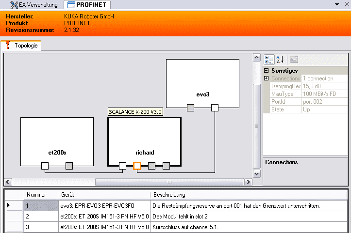 If errors occur during operation of a robot, for example due to defective wires or peripheral components, users have to determine the cause of the errors quickly and reliably. The DTMs are provided with tools for this purpose. These range from monitoring I/Os and analyzing fault memories on the devices all the way to very detailed analyses, such as determining envelope delay times or damping reserves in fiber-optic cables.
Use of FDT Technology with KUKA robots.
 All robot control systems from KUKA that are shipped with Firmware Version 8.0 and newer are commissioned using FDT Technology. The supported fieldbuses range from the conventional fieldbuses DeviceNet, PROFIBUS, and INTERBUS to the new Ethernet-based systems EtherCAT, PROFINET, and EtherNet/IP. Complex scenarios via cascaded gateways and proxies are also implemented using standard FDT Technology.
Main tasks in developing DTMs
The implementation scenarios to date have shown that the main effort in developing DTMs lies in the interpretation of device description files. This is owing to the company-specific focus on the generic device DTMs. The newer XML- based formats such as GSDML, FDCML, and ESI offer noteworthy simplifications compared to the traditional text-based formats GSD and EDS, because they can rely on tried-and-tested XML parsers. Consequently the interpretation of syntax and grammar is no longer required.
Further potential of FDT/DTM Technology.
For a control system manufacturer supporting many different bus systems, FDT DTM technology offers great strengths. The high interoperability between the DTMs provides interesting strategic considerations for make or buy decisions.
 The enhancements available in FDT 2.0 will further improve the user experience. In FDT 1.2, the user interfaces are not always implemented consistently in accordance with the FDT style guide, and the frame application has no influence on this. In FDT 2.0 there are enhancements which permit the FRAME application to render parts of the user interface.
Adherence to the corresponding FDT 2.0 style guide is also checked during the FDT 2.0 DTM certification process.